INTRODUCTION
Satellites are launched into many different types of orbit around the Earth for many different reasons. All of these orbits however, share one characteristic. They follow an elliptical path with the centre of the Earth at one focus of the ellipse. This ellipse can be specified be a set of parameters. However, this does not completely define the orbit, because an ellipse lies in a plane and that plane can be oriented in many different ways relative to the Earth's geometry.
It turns out that six number suffice to totally specify the parameters of a satellite in orbit about the Earth (or a body in orbit about the Sun). If we know these numbers we can then calculate where a satellite will be at a future time.
This note is concerned with what those numbers are and how they are specified.
SPECIFICATION
As stated above, there are two basic aspects to the motion of an object in orbit:
ORBITAL SHAPE AND SIZE

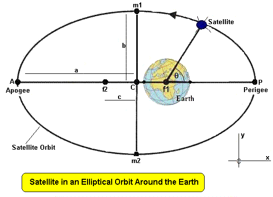
The above image represents a satellite in an elliptical orbit around the Earth. The long or major axis of the ellipse is the length AP and the short or minor axis of the ellipse is the length m1-m2. The ellipse can be specified by two quantities, the semi-major axis a and the semi-minor axis b. The two points f1 and f2 are called the foci (plural of focus) of the ellipse, and the Earth is always at one focus of the ellipse, in this case f1. The distance of the foci to the centre of the ellipse is c, and c2 = a2 - b2.
The shape of the ellipse is defined by the relative values of a and b and is specified by another quantity e, the eccentricity of the ellipse, where
The point P is called the perigee of the orbit and this is where the satellite is at its closest point to the Earth. The point A is called the apogee and this is where the satellite is at its furthest distance from the planet. Perigee and apogee distances can be calculated using :
p = a ( 1 - e ) ... perigee
It is customary to specify the shape and size of the orbit by the two parameters:
The orbital period depends only upon (and can be calculated from) the semimajor axis and the mass of the Earth (M):
ORBITAL ORIENTATION
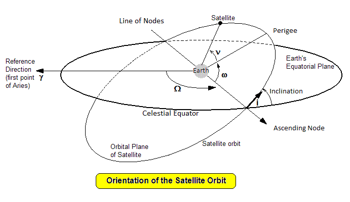
The celestial equator is the projection of the Earth's equator onto the sky, and forms the reference plane with which to describe the orientation of the satellite orbit. The reference plane is also the Earth's equatorial plane. The points at which the satellite orbit crosses this reference plane are called the nodes of the orbit (the ascending node is where the satellite is moving from below the reference plane to above it, the descending node is where it moves from above to below).
Three angles are needed to describe the orientation of the orbit with respect to the Earth. (1) i - the inclination of the orbit is the angle between the orbital plane and the reference plane (ie the celestial equator), (2) Ω is the angle between the line of nodes and a reference line in the reference plane. This reference line points to an astronomical point in the sky known as the first point in Aries (a constellation). It is designated by γ (3) ω is the angle between the line of nodes and the semimajor axis of the ellipse in the direction of perigee. This angle is measured in the plane of the orbit.
The angle ν is the angle from perigee to the satellite. This is called the 'true anomaly' of the body. Many orbital element specifications also refer to a 'mean anomaly' which refers to an angle which goes out to a sphere circumscribed around the ellipse. One can be calculated from the other using a formula that is called "Kepler's equation". The position of the satellite is computed at any specified time t by knowing both the time of perigee passage and computing the mean anomaly M from the time t and and the satellite's period P. M = 2 π t / T radians. The true anomaly is then calculated from the mean anomaly by Kepler's equation M = ν - e sin ν .
ORBITAL ELEMENTS
The position of an orbital space object can thus be specified by six parameters:
However, they are not the only way to specify the position of an object.
The US Strategic Command, which operates the US spacetracking network issues space object orbital information in a form they call TLE (Two Line Elements) because the specified parameters are printed over two lines. The actual six parameters used are a modification of the six elements we have used previously.
To calculate the satellite mean anomaly you subtract the the TLE time from the satellite prediction time and multiply the result by the mean motion n.
TLE FORMAT
A typical TLE has the format:
2014-037E
1 40073U 14037E   14195.06978695  .00000547  00000-0  79836-4 0   207
2 40073  98.4035 246.9202 0004647 235.4646 124.6133 14.80036563   782
The first or header line is the name of the satellite or object in question. The next two lines contain the actual elements.
This TLE thus specifies the orbital elements for a space object referred to as 2014-037E, one of a group of satellites launched by the Russians in 2014. The E means that it was the 5th object put into orbit by the one launch vehicle.
The format of the following two lines is as follows:
Line 1
  Group 1   Line number (= 1)                      column 1
  Group 2   NORAD catalog number follower by       columns 3 to 7
            classification (U=unclassified)        column 8
  Group 3   International designation =
            Last two digits of year +		   columns 10 & 11
            Launch number of the year +            columns 12 to 14
            Object number deployed (alphabetic)    columns 15 to 17
  Group 4   TLE epoch date (yyddd.dddddddd)        columns 19 to 32
  Group 5   Rate of change of mean motion          columns 34 to 43
  Group 6   Second derivative of mean motion       columns 45 to 52
  Group 7   Atmospheric drag term                  columns 54 to 61
  Group 8   Ephemeris type  (=0)                   column 63
  Group 9   Element set number                     columns 65 to 68
  Group 10  Checksum (to check data integrity)     column 69
Line 2
  Group 1   Line number (=2)                       column 1
  Group 2   NORAD catalog number                   columns 3 to 7
  Group 3   Orbital inclination (degrees)          columns 9 to 16
  Group 4   RAAN (degrees)                         columns 18 to 25
  Group 5   Orbital eccentricity                   columns 27 to 33
            (leading decimal point is assumed)
  Group 6   Argument of perigee (degrees)          columns 35 to 42
  Group 7   Mean anomaly (degrees)                 columns 44 to 51
  Group 8   Mean motion (revolutions per day)      columns 53 to 63
  Group 9   Revolution number (orbit number)       columns 64 to 68
  Group 10  Checksum (modulo 10)                   column 69
Thus for the above TLE, the satellite has a NORAD designator of 40073, and a COSPAR(International) designator of 14037E. The latter means that is was the 5th object deployed from the 37th launch of the year in 2014.
The date or epoch of the TLE is day 195 of year 2014. The fractional part of the date (0.06978695) gives a time of 01:40:29.7 UT.
The mean motion of the object is 14.8003.. revolutions per day and the change in this motion is 0.00000547 rev/day/day. Groups 6 and 7 are usually not very accurate and are often not used in orbit prediction programs. (The last two characters of theses two groups are the exponent of the number).
The orbital inclination is 98.4.. degrees. Any value over 90 degrees indicates a retrograde orbit which indicates it moves over the Earth's surface from east to west, whereas a prograde (normal) orbit moves from west to east.
The right ascension of the ascending node is 246.0.. degrees, the argument of perigee is 235.4.. degreesa and the mean anomaly is 124.6 degrees.
The eccentricity of the orbit is 0.0004647 which being so close to zero indicates a near circular orbit. The mean motion of the orbit is 14.800.. revolutions per day, which indicates an orbital period of 97.3 minutes.
The numbers at the end of each line indicate that this is the 20th set of elements (TLE) issued for this satellite and that the +satellite was on its 78th orbit at this time.
The following TLE is for practice. After decoding the elements use the previous information to deduce the approximate altitude of the satellite, which is the first Australian communications satellite.
OPTUS A1 (AUSSAT 1)
1 15993U 85076B   18165.48109566 -.00000294 +00000-0 +00000-0 0  9999
2 15993 015.3011 003.5014 0006102 312.6931 228.2493 00.99759997090415
TLE AVAILABILITY
Two line elements are available from a number of web sites. Dr Tom Kelso makes available TLEs for a range of different satellites at <celestrak.com>.
US Stategic Command tracks tens of thousands of objects in Earth orbit and access to the TLEs for these objects is available at <www.sat-track.org> to approved customers. Application for approval is made via the same web site. This data base does not include US military satellites.
DECODING THE TLEs
All satellite prediction programs include preprocessors that decode the TLE format into orbital elements for subsequent processing. However, a small stand alone TLE decoder allows a quick look at the orbital status of a particular satellite.
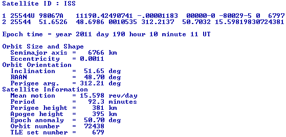
Code for such a TLE decoder (in the BASIC language) is presented here for educational purposes. Using this on the file iss.tle for the International Space Station should result in the output shown below:
THE REAL WORLD
Unfortunately life is not quite as simple as we would like. The Keplerian elements are only truly correct for the time of issue. They gradually change over time due to perturbating forces acting on the satellite. These forces change depending upon the orbital altitude of the object. Perturbing forces can be divided into two types:
DISSIPATIVE PERTURBATIVE FORCES
Conservative forces can be calculated and do not change the total energy of the space object. Dissipative forces change the total energy of the object they act upon and are in general more difficult to deal with than conservative forces.
The end result of perturbations is the TLEs have a limited life for orbital prediction and new TLEs need to be acquired at regular intervals. For objects in very low orbits (eg below 300 km) they become unusable in a day or so. Generally LEO objects TLE need to be updated every few weeks, sometimes weekly.
For space objects in higher orbits, such as geosynchronous orbit, TLE lifetime is generally longer maybe as much as a few months.
STATE VECTORS
The accuracy of TLEs issued by US Strategic command will rarely give orbital positions to better than 100 metres and typically only to a kilometre. In cases where higher accuracy is required orbital positions are specified not by orbital elements but by quantities called 'state vectors'. These specify the three dimensional position and velocity of an object at a given time. There are thus three position coordinate numbers and three velocity numbers. Thus we see that six quantities are still required to specify the orbit and satellite location.
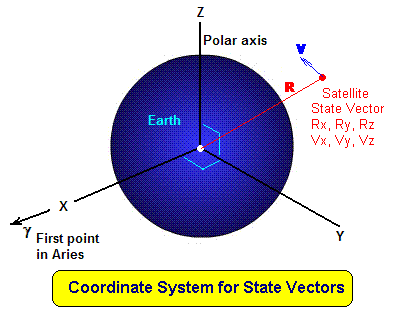
The six vector components required to specify the state at the time t are then Rx, Ry, Rz, Vx, Vy and Vz.
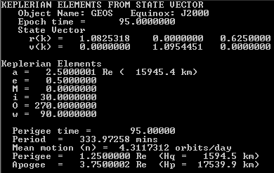
Although these can be used by orbital propagation programs they don't give humans any idea of the orbital parameters. It is thus useful to be able to convert from state vectors to orbital elements. A simple BASIC program to do this is included here. If used with the data file satvec.dat it should produce the output:
 Australian Space Academy