Some of the material here was first presented at the Third National Space Engineering Symposium, Canberra 30 June-2 July, 1987.
INTRODUCTION
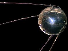
The first artificial satellite, Sputnik-1, launched into orbit on the 4th of October 1957, carried a radio beacon transmitting on the frequency of 20.005 MHz. This could be received by a sensitive short wave receiver on the ground, and many people heard the beep-beep-beep sound of this satellite as it orbited around the Earth every 90 minutes or so. It served as an announcement of its presence to the world and allowed it to be tracked by ground stations. It is also thought that the duration and spacing of the beeps carried information about the conditions in the satellite. This was the first instance of telemetry (measurement from afar) from space.
Scientists quickly discovered that the signals from such a beacon could be used to gather information about the state of the Earth's upper atmosphere, in particular the region of the atmosphere containing charged particles called the ionosphere.
Satellite beacons have been used for a variety of purposes, ranging from tracking and telemetry through propaganda and advertisement to ground navigation and monitoring. This note will explore in more detail some of these purposes.
HISTORY
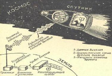
Following Sputnik-1 came Sputnik-2. This carried a live dog (Laika) into space. Not only was a beacon needed to track the spacecraft and telemeter information about its health, but it was also needed to relay information about the dog's condition. The cartoon below was published by a Russian newspaper of the time illustrating the essential details.
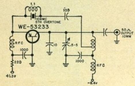
Following the Russian successes, the Americans launched satellites in the Explorer series and then in the Vanguard series. The early US satellites carried beacons that transmitted on 108 MHz. Slightly later satellites used frequencies in the newly created 'space' band at 136 MHz.
The circuit diagram of the beacon on Vanguard-1 is shown below.
Satellite beacons today are considerably more complex, generally transmit on higher frequencies and are controlled by digital logic circuitry (eg computers).
TYPES OF BEACONS
Satellite beacons may be classified according to their function or according to the frequency they use, or a mixture of both. The table below lists some major categories of satellite beacons.
| Beacon Function | Band | Notes |
| Early Russian tracking and telemetry | HF | eg 20.005 MHz |
| Early USA tracking and telemetry | VHF | eg 108 / 136 MHz |
| Geosat tracking and telemetry | Ku / Ka bands | eg 14/26 GHz |
| Deep Space tracking and telemetry | S / X bands | eg 2 / 8 GHz |
| Ionospheric studies | VHF / UHF | GPS now commonly used |
| Tropospheric studies (rain attenuation) | Ku / Ka bands | 14 / 26 GHz |
| Navigation | L - band | eg GNSS / GPS |
| Optical | Visible light | Mostly experimental |
BEACONS FOR IONOSPHERIC RESEARCH
The ionosphere is a region of the Earth's upper atmosphere (altitude about 80 to 1000 km) ionised (to form a weak plasma ) by UV and X - radiation from the Sun. This region affects radio waves passing through it, producing refraction, absorption, scintillation and other effects. The refractive index of the ionosphere is given by:
where f is the radiowave frequency and fp is the plasma frequency given by:
fp2 = Nee2 / (4π2ε0me)
As long as f is greater than fp the radio wave can pass through the plasma and transionospheric propagation is possible.
Satellite beacons used for ionospheric research normally transmit in the VHF (30-300 MHz) or UHF (300 - 3000 MHz) bands. They should be above the ionospheric critical frequencies (typically less than 30 MHz) so that the signal will penetrate the ionosphere, but they should not be at too high a frequency or sensivity to ionospheric parameters is reduced (most ionospheric characteristics show a variation according to the inverse square of the frequency - 1/f2).
A block diagram of a satellite radio beacon transmitter ideally suited for ionospheric studies is shown below.
The beacon employs three widely spaced phase-locked frequencies. The frequency range covered allows for the examination of ionospheric irregularity structures over a wide spectral range - for the derivation of a spectral power law in observed ionospheric scintillation. Two widely separated frequencies allows for accurate determination of ionospheric total electron content (TEC). The highest frequency essentially acts as a reference to the low frequency which shows a high sensitivity to TEC. The phase locked relationship between the frequencies allows differential phase comparison. The relatively high transmitter output (2 watt) allows the beacon to be used in geosynchronous orbit (GEO) as well as in low Earth orbit. The presence of a modulating signal (usually a pseudo-random binary code) allows for the measurement of differential time delay between frequencies.
The most common ionospheric measurements made using satellite beacons are (1) Faraday rotation, (2) Delay due the ionospheric line of sight electron content, and (3) Signal scintillation.
MEASURING FARADAY ROTATION
Instruments used to determine the Faraday rotation angle of a satellite radio beacon signal and monitor its change with time are called polarimeters. The basic principle is to rotate a linearly polarised antenna until a maximum or minimum signal is obtained. The antenna can be rotated mechanically or several stationary antennas can be employed in a switched arrangement to electronically simulate rotation. The output of the system is a time history of Faraday rotation angle. If required, this may be converted into TEC using a model of the Earth's magnetic field.
MEASURING TOTAL ELECTRON CONTENT
Differential time measurements, sometimes called differential Doppler measurements, may be performed in one of two ways. Two of the frequencies (the lowest and the highest) may be coherently downconverted and then divided to produce a common reference frequency. A phase comparison is then performed at this common frequency to determine the phase difference between the two frequencies. An ambiguity can exist in the output of the comparator, especially if the reference frequency is high. This ambiguity, which must be resolved by other data or knowledge, is 2nπ in phase, where n is the unknown integer to be determined. The output data stream is a time history of TEC.
The second type of differential time measurement is often referred to as group path delay. It relies on a modulation frequency common to both signals. In the ideal case of binary modulation, the zero crossing of the fastest signal (highest frequency) would be used to start a time counter. The zero crossing of the lower frequency would then be used to stop the counter. The time interval measuired is a direct measure of TEC. In practice the modulation frequencies of each signal may require downconversion (or division) to effectively expand the time measurement required . In this way, time differences of milliseconds, rather than microseconds or even nanoseconds can be made, with a resultant increase in accuracy.
MEASURING IONOSPHERIC SCINTILLATION
Amplitude scintillation measurements can be made with simple equipment. A narrowband low noise AM receiver connected to a suitable display to show the signal amplitude/intensity is the simplest configuration. The main requirement for this type of system is a high signal to noise ratio, so that signal scintillations do not saturate the receiver or fall below the noise level. A high SNR can be achieved with a high beacon power, a low noise receiver and/or a large receiving antenna (high gain).
IONOSPHERIC SATELLITE BEACON STATUS
In the early days of space research, there was a multitude of VHF beacons on both geosats and satellites in low Earth orbit for ionospheric research. Today, in the 21st century there are very few such beacons, especially phase coherent multi-frequency VHF beacons. Ionospheric researchers have thus turned to the readily available and prolific GPS beacons to continue ionospheric research.
While these monitors are ideal for some purposes, the high frequencies used (L-band) do not have adequate resolution/sensitivity to support lower frequency systems and applications (eg low frequency radio astronomy).
BEACONS FOR TROPOSPHERIC RESEARCH
Satellite beacons above X-band are affected little by the ionosphere. However, as the frequency is increased, the beacon starts to be affected more and more by the troposphere, the first 10 km of the Earth's atmosphere is which our weather occurs.
The refractive index of the troposphere to microwave signals is given by:
where the refractive modulus N is given by:
and where P is the atmospheric pressure in Pascal (Pa), Pwv is the water vapour partial pressure (Pa) and T is the temperature in Kelvin. This formula is accurate to N<0.1 over the frequency range 1 to 50 GHz.
Note that standard atmospheric surface pressure is 101.3 kPa (= 1013 millibar), and 20 Celsius = 293 Kelvin.
As the pressure, temperature and water vapour change with altitude, geographic location and time, the troposphere thus produces bending (refraction), attenuation (absorption) and scintillation (variable amplitude) of high microwave band satellite to ground signals.
At VHF and UHF frequencies very long periodic fadings (5 to 30 min) have been observed on 130 and 400 MHz transmissions of geostationary satellites and these have been correlated with cold fronts, ground and elevated temperature inversions.
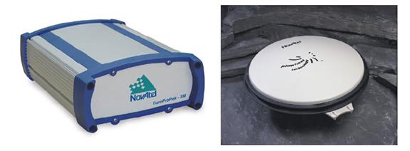
|
 Left: Ka band beacon receiver developed at James Cook University. Above: Rain fade detected by the receiver. (Images after Kikkert & Kenny JCU) |
BEACONS FOR TELEMETRY AND TRACKING
Satellite beacons are often used to telemeter data concering the health of the spacecraft and its environment. Such data may include the status of the various satellite subsystems, the power output of the solar panels and the current drawn by the various pieces of equipment, the satellite temperature, orientation (gyro status) and the external magnetic field, solar flux and radiation environment, etc.
In the early satellites, data was transmitted in analog form using various multiplexing schemes. Tones, frequency and time division multiplexing on a single carrier or several sub-carriers were used. Nowadays, data is almost always sent in digital form and often in packets using standard protocols. Various error correcting schemes are used to mitigate noise on low signal levels.
Although hardware decoder designs are available, software is increasingly used to decode satellite telemetry. This often requires only a simple preprocessor before input to the decoding PC. A simple infinite clipping processor schematic is shown below, which acts as an interface between a satellite receiver and a PC serial port. Often times the receiver output is fed directly to the sound card of a PC.
With the advent of smallsats and particularly low cost cubesats and the ability of some launchers to place dozens of these into orbit at the one time, there is now a plethora of these satellites in orbit transmitting telemetry down to Earth with an inadequate number of receiving stations around the globe to ingest the data. Many of the satellite owners (often universities with limited funds) are pleading for people to receive and send them the data from their vehicles. There is thus a great opportunity for individual participation in this field.
The FunCubeSat organisation in the UK is making available a small receiving 'dongle' that can be connected between an antenna and a USB port of a PC to enable reception and decoding of such satellite telemetry.
For more information see FunCUBE dongle. Individual cubesat (and other smallsat) web sites often have details of their telemetry format.
Commercial geosynchronous communication satellites use a beacon for tracking purposes. These are often K-band beacons as the higher frequencies (and thus shorter wavelengths) allow for more accurate radiometric measurements (range and velocity).
OPTICAL BEACONS
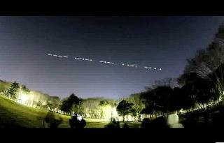
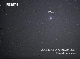
Most beacons carried by satellites have transmitted radio frequencies. However, an unusal satellite built by Japanese engineering students at Fukuoka Institute of Technology in Japan carried a high intensity LED modulated by Morse code to make visual patterns across the sky as seen by a ground observer.
 |
|
A few other satellites have carried xenon flashtubes for optical beacon test purposes.
AN IONOSPHERIC BEACON GROUND STATION
Satellite radio beacons offer a good opportunity to introduce students to the elementary concepts of space systems - acquisition, tracking, downlink signal calculations, data decoding and display, as well as a study of the near-space environment. The figure below outlines a system to monitor ionospheric total electron content (TEC) from Faraday rotation measurements. A knowledge of both is important in satellite communications, tracking and also in radio astronomy.
All components of the system are essentially 'off-the-shelf'. The two non-standard items are the antenna switching unit and the polarisation decoder unit. Both of these are now available as one package in the form of a radio direction finding adaptor from Dick Smith Electronics (catalog K-6345). In its intended application these two devices are used with an FM receiver to simulate a rotating antenna. The rotation results in a sinusoidal Doppler shift or frequency variation.
The 'decoder unit' performs a phase comparison of the received signal variation with the reference switching frequency to locate the direction of the incident signal. This process is exactly that required to measure Faraday rotation. In this instance the four switched antennae have linear polarisations offset in steps of 45 degrees. (With a little ingenuity and vector addition of signals, two orthogonal antennae are sufficient.) A single antenna with a contiuously rotating plane of polarisation is thus simulated. Comparison of the signal, suitably amplified by the receiver, from this 'virtual' rotating antenna with the reference signal indicates the required plane of polarisation.
The output indication is by 32 front panel LEDs. A 5-bit digital representation of this is readily available within the device (small circuit variations could increase this to 6 bits for greater accuracy). This digital signal could be fed to a PC for display and archive purposes. Regular diurnal variations in the plasma density of the ionosphere will be readily apparent. On some days ionospheric storms may be noted.
REFERENCES
EA Cohen, "25 Years of Satellite Beacon Studies", The Australian Physicist, v21, pp224-226 (1984).
 Australian Space Academy