Newton's laws allow the motion of a planet around the Sun to be computed fairly readily, as long as only two bodies (the Sun and the planet) are considered. However, the problem of three bodies is much more difficult. There is nothing in the physics of the laws which prevents a solution, only the complexity of the mathematics involved.
Many mathematicians worked on the problem of three-body motion in the 1700's and even today only restricted three-body problems have been found to have analytical solutions, although perturbation theory and numerical methods using computers allow planetary orbits involving the forces from all major solar system bodies to be calculated with high precision.
A publication in 1760 by Leonhard Euler indicated the presence of the stationary points now labelled L1, L2 and L3. In 1772 Joseph Louis Lagrange predicted the points L4 and L5 and in volume 6 of his collected works in 1773 he implied the existence of all five stationary points. None of these works were accompanied by a diagram, and it is not known when the first diagram appeared and when the naming and numbering of the stationary points was first proposed.
However, it does appear that NASA was responsible for gradually shifting most people to the L2, L1, L3 convention in the 1970's. This may have been to give greater emphasis to the point between the two primary bodies, which is the only point that exists in a non-rotating system (although of course, in a non rotating system there is no stability and the two main bodies move toward each other and the system collapses!). It may also have been because the point between the two bodies was the first Lagrange point to be used in placing satellites.
In general the astronomical community may prefer the original numbering scheme whereas the space community almost universally uses the sequence L2-L1-L3. However, Lagrange point labelling is a matter of convention. There is no right or wrong. We use what we believe is the original naming convention in this document.
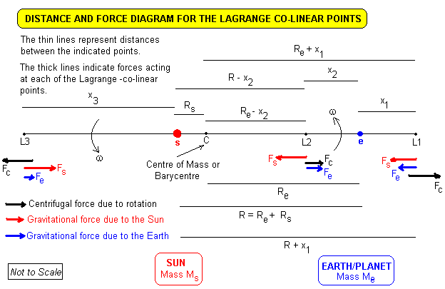
The five stationary points exist because the true gravitational forces exerted by both the Sun and the planet are just cancelled by the centrifugal force at these points. At any point within the plane there are two gravitational forces (per unit mass), one due to the Sun (G Ms / Rs2) and one due to the planet (G Mp / Rp2), where Ms and Mp and the respective masses of the Sun and the planet, G is the Newtonian gravitational constant, and Rs and Rp are the distances from the point to the Sun and planet respectively. The centrifugal force per unit mass is given by r ω2 where r is the distance from the point to the center of mass and ω is the angular velocity of the rotating reference frame.
The gravitational forces all are directed toward the massive body in question, whereas the centrifugal force is directed away from the centre of mass (barycentre).
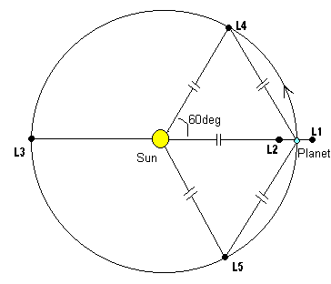
The points L1, L2 and L3 all lie along the line joing the Sun and the planet. Derivation of their positions along this line will be shown in the next section.
Points L4 and L5 lie at the vertices of equilateral triangles whose base joins the Sun and planet (or planet and moon), as shown in the diagram below for L4.
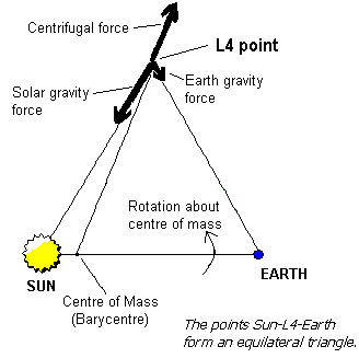
The centre of mass of the Sun-Earth system is shown outside the Sun here for clarity. It actually lies within the core of the Sun, less than 500 km from its centre. However, this distance is just enough to ensure that all three forces at the L4 point can balance. To prove that the triangle is equilateral (equal side lengths) requires that the three forces be resolved into orthogonal components and added algebraically.
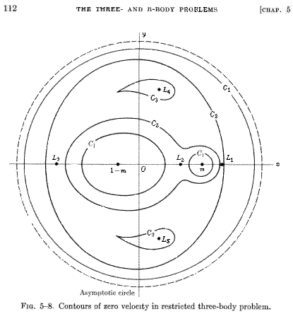
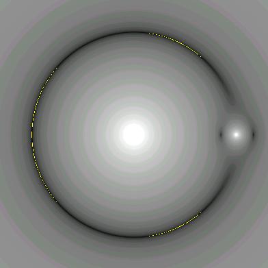
The diagram below shows the magnitude of the total force in the Sun-Earth rotating system. Very bright regions signify a strong force field, whereas dark regions are regions of weak field. The yellow lines indicate forces close to zero, and show that L3, L4 and L5 are really quite extended areas rather than points. This is confirmed by the distribution of Trojan asteroids discussed in a later section. The intensity scale of this image is logarithmic in force and has also been allowed to saturate at high field strengths to better show the weak field detail. Note that L1 and L2 are elliptical areas with the major (longer) axis perpendicular to the Sun-Earh line.
The force equations for the three Lagrange points are:
| System | Sun-Earth | Earth-Moon | Sun-Jupiter |
| Major body mass M(kg) |
Sun 1.991x1030 |
Earth 5.98x1024 |
Sun 1.991x1030 |
| Minor body mass m(kg) |
Earth 5.98x1024 |
Moon 7.35x10²² |
Jupiter 1.899x1027 |
| Mass ratio m/(M+m) |
0.000 003 | 0.012 | 0.000 953 |
| Distance M to m |
149,600,000 km 1.000 000 AU |
384,401 km | 778,300,000 km 5.206 AU |
| Distance M to CM |
449 km | 4,667 km | 741,629 km |
| Distance m to CM |
149,599,551 km 0.999 997 AU |
379,734 km | 777,558,403 km 5.197 AU |
| Distance L1 to m |
1,501,557 km 0.010 037 AU |
64,499 km | 54,293,950 km 0.363 AU |
| Distance L2 to m |
1,491,557 km 0.009 970 AU |
58,006 km | 51,879,339 km 0.347 AU |
| Distance L3 to M |
149,599,737 km 0.999 998 AU |
381,678 km | 777,867,410 km 5.200 AU |
The values used in the above table are mean values for the planetary distances. As all of the bodies move in elliptical orbits these values change from moment to moment. We may thus ask if the values in the table should be quoted to the nearest kilometre, and the answer of course is no, except in the comparison of two values that differ by only a few tens of kilometres. It should also be noted that we have used a value for the Astronomical Unit (which is defined as the mean distance between the Sun and the Earth) of 149,600,000 km. A more accurate value is in fact 149,597,871 km but the rounded value chosen is easier for comparison purposes.
So bear in mind that all the values in the above table are approximate values. They vary from moment to moment due to the non-circularity of the orbits and are subject to perturbations from other bodies in the solar system. Lagrange himself did not believe that these points would be of significance in the solar system, but the fact that even some distance away the forces acting on a small body are quite small gives these points a physical reality.
Note that only in the Sun-Jupiter system is the barycentre (centre of mass, CM) outside the larger body (in this case the Sun) which has a radius of 695,950 km.
L4 and L5 are conditionally stable. As long as the mass ratio (as defined in the previous table) is less than 0.0385 and the small mass at either L4 or L5 has both a limited displacement and only a small velocity, it will stay in the general area of the point. This point, under the given conditions, may be likened to a ball sitting in a depression on the top of the hill. If its velocity is too great it will move out of the depression and down the side of hill, but if it is only moving slowly it will stay confined to the depression.
However, even at the unstable points, it is possible to set a spacecraft in a reasonably stable orbit around these points. This may be an orbit that circles the point. Stability analysis (see Introduction to Celestial Mechanics by S W McCuskey, Addison-Wesley, 1963) shows that an elliptical orbit both in the orbital plane and out of it are reasonably stable at the co-linear points.
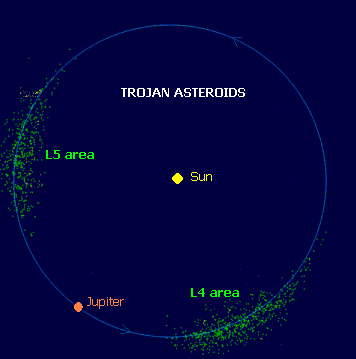
The Sun-Jupiter system has the greatest number of these asteroids and they are called the Trojan asteroids or simply Trojans. As of July 2011 a total of 4917 Trojans have been found in this system, 3168 around the L4 point and 1645 around the L5 point. The diagram below shows the distribution of these asteroids at one point in time. Notice the enormous spread, over a distance of more than 500 million kilometres along the orbital path. This shows the region over which the stability of the area extends.
As of mid-2011 eight trojans have now been discovered in the Sun-Neptune system and four in the Sun-Mars system. One possible trojan in the Sun-Earth system was recently discovered, but stability analysis has yet to confirm how permanent this may be.
It was once thought that the gegenschein, a very faint patch of light at the midnight zenith, similar to the zodiacal light, may be due to interplanetary dust particles orbiting the Sun-Earth L1 point. This has still to be investigated further.
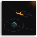
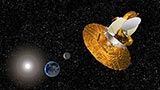
From L2 a spacecraft can continuously monitor the solar wind and space weather from the Sun before it reaches the Earth. On the average they can give about one hour's warning of an event. Three such spacecraft are SOHO, ACE, and WIND. These have halo type orbits about L2, not just for stability, but to actually keep them away from a direct line of sight from the Earth to the Sun. This is so that ground stations downloading their data, do not have to point their antennas at the Sun, which is a powerful radio source that can easily overwhelm the signal from the spacecraft transmitters.
It is interesting to note that the replacement for the Solar Heliospheric Observer (SOHO), the Solar Dynamics Observer (SDO) was not placed at L2, but in geosynchronous orbit. The project scientists and engineers for SDO decided to accept the eclipse periods that come with geosynchronous orbit to enable an extremely high downlink data rate (several gigabytes per day), which simply cannot be supported by the current NASA Deep Space Network from the L2 point.
Spacecraft placed at the L1 point (beyond the Earth away from the Sun) tend to be astronomical in purpose. Examples are WMAP, Herschel and Planck. These spacecraft need shielding from the Sun (the Earth partially covers the Sun at this point) to enable their sensitive detectors to be kept as cool as possible and to cover as much dark sky as possible. At the same time their solar cells also need a reasonable amount of sunlight to power the spacecraft.
 |
This is how the Sun appears from the Sun-Earth L1 point. The Sun subtends an angle of 0.528o or 31.7 minutes of arc, whereas the Earth subtends an angle of 0.487o or 29.2'. The Earth thus covers 85% of the solar disc. If the Earth did not occult the Sun, the solar power at L1 would be 1343 watts per square metre (compared to 1370 W m-2 at the Earth). However, the actual solar power received will be less than 200 W m-2 due to the presence of the Earth. The actual value will be less than 15% of 1343, due to the phenomenon of solar limb darkening. Of course, spacecraft will not be stationed right at L1, but will orbit about the point, and thus will have access to more solar power. |
Note that all of these spacecraft, whether at L1 or L2 have to expend station keeping fuel to keep them in appropriate orbits for any length of time.
Finally, it should be noted that the Lagrange points offer very low energy transfer points for spacecraft on their way to and from other parts of the solar system. They enable new orbital dynamics for fuel-strapped missions of exploration.
 Observing the Sun SOHO/L2 |
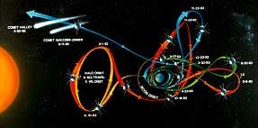 Lagrange point transfers ISEE-3 |
 Mapping the Cosmic Microwave Background WMAP/L1 |
 Home
Home